
Face Type and Method

Type and Method are fields that give a description of the purpose and method for each sample line. STOPECALCTM recognizes five different face types to fit different development samples. When creating or editing a face, the user may select the face type (Type) from the drop-down list in the face description area. Face type is primarily informational, but it can be used to filter faces for reports.
Method refers to the sampling orientation relative to the vein or bed. The actual calculations of tonnage and grade are not affected by the sampling method. Like Type, Method is chosen from a picklist in the field box. Faces may be imported without a method specified, but a method must be chosen if a face is created within STOPECALCTM.
TYPES
Face
Face as face type is likely to constitute a significant portion of all development samples. Faces can be any channel sample line with geometry applied: faces, raise or rib samples.
Stope
Samples taken along the back of a cut-and-fill or shrinkage stope lift can be labeled Stope samples. Grade and tonnage will likely be reported using the Face Report rather than by creating Rounds.
Split
Consider the case in the example below where a face is driven wide through a vein splay intersection. If the splay doesn't carry economic values, the drift may be continued narrower from that point onward. Below is the initial drive:
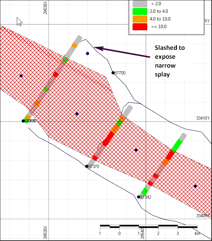
The narrow interval on the north side of the face won't carry the full width, so the drift is narrowed in the next blast:
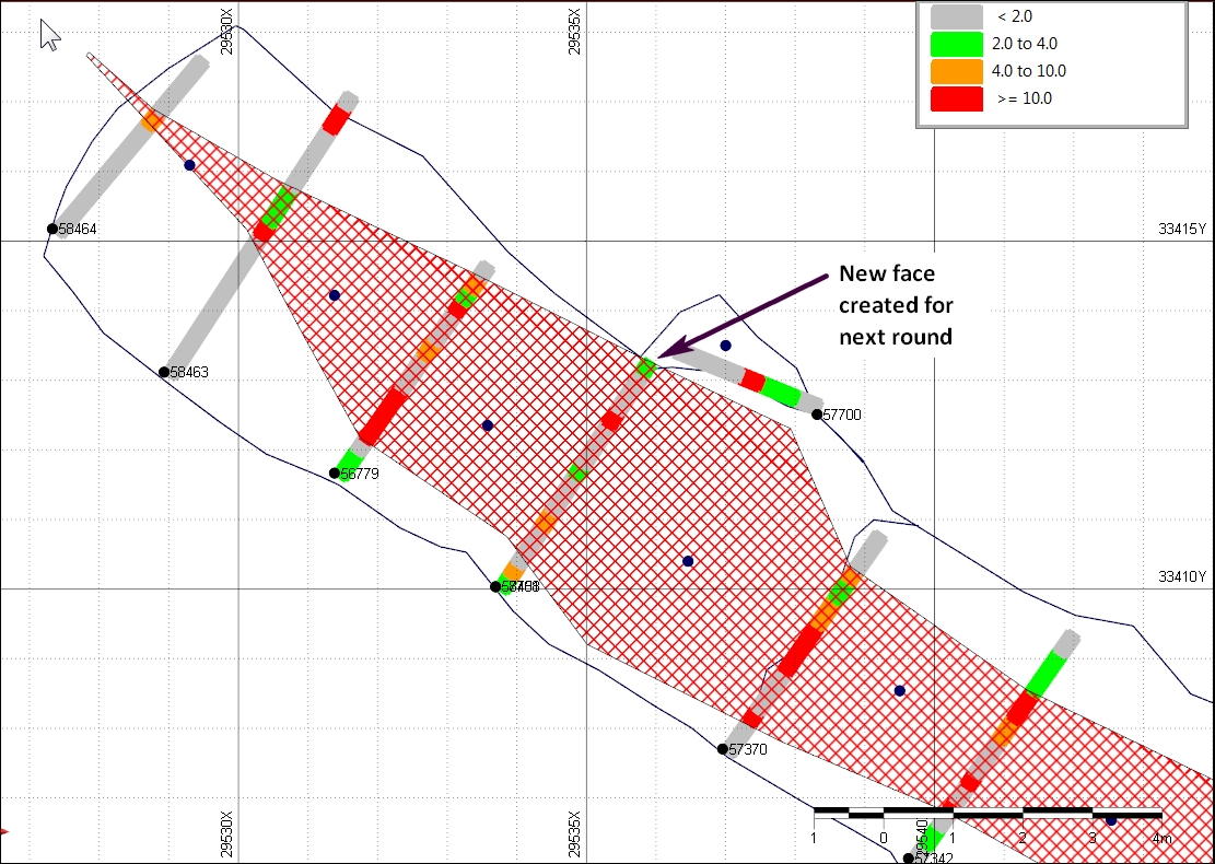
In order to define the tonnage and grade of the next round, the face is split by copying header and interval information to a new Index#. The length is changed and the intervals extending into the slash portion of the previous face are deleted. Start coordinates are identical, but new central coordinates must be entered for the shortened face. Thus, two faces are necessary to account properly for the tons and grade mined. They will partially overplot each other in any mine package. This type of operation takes some creativity and manual adjustment--no mining package or other utility will provide these adjustments which make the STOPECALCTM approach unique.
Slab
In some cases, extra sampling may be done to characterize tonnes and grade of small slashes or slabs taken in development headings. It may not be feasible or desirable to append addtional samples to an existing sample line, and it may be more accurate to define a new face for the additional volume taken. This is preferred to arbitrarily assigning tonnes and grade, or characterizing all slashes as dilution. Slabs will not normally constitute more than 5 - 10% of tonnage and grade. An example of a slab round is shown below:
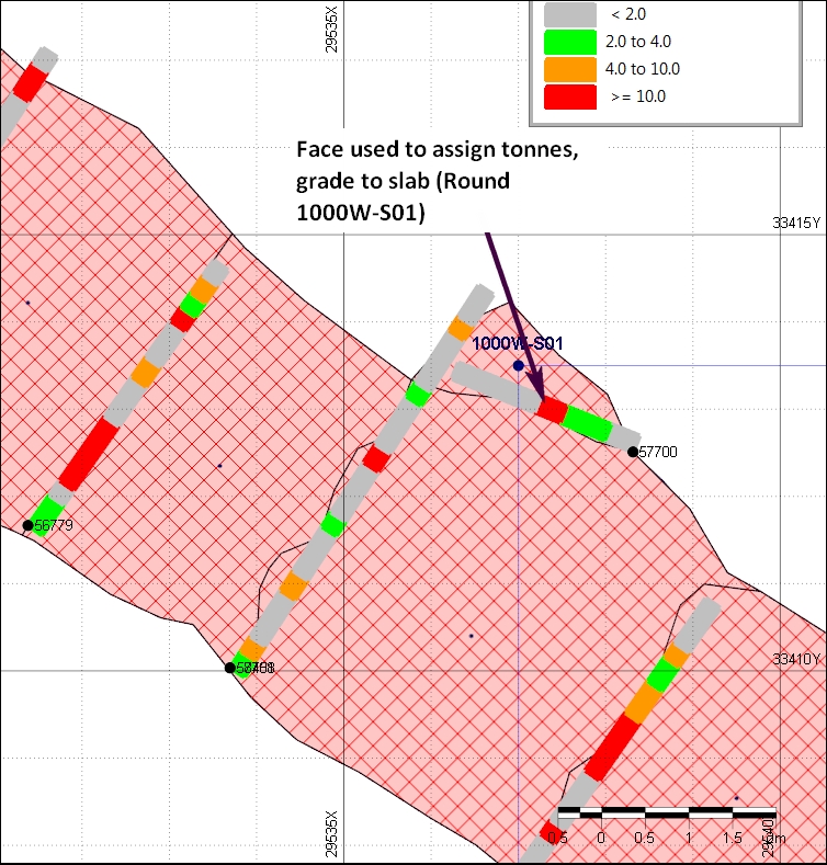
In this case, a rib sample line was chosen to assign dimensions, tonnes and grade. The geologist could instead split the face illustrated above to do this, depending on which in the particular circumstance is the most logical or representative choice.
Dummy
This is a catch-all, but has been used when creating a face from a portion of a rib sample line; e.g., when initiating a new drive on structure from a cross-cut drift. There is no face per se, but a "dummy" face can be created from existing data to estimate the ensuing round tonnage and grade. Examples are shown below:
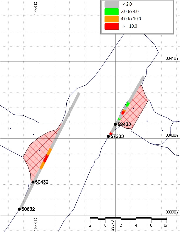
Dummy faces 58432 and 58433 have been created from the portions of rib sample intervals in channel lines 58632 and 57303 that bound the initial blasts made in the new ore development.
SAMPLING METHODS
HW
Horizontal width (HW) is generally the preferred method for sampling steeply dipping structures and generally is the safest method. In the case of sampling a backstope that follows a dipping vein, as long as the sample line is perpendicular to the vein dip and the height measurement is taken along the dip, this method is appropriate.
TW
True width (TW) sampling will be accommodated (in future versions, according to customer requirement) by STOPECALCTM using the sample line dip to correct the widths. The user must enter the face width measurement in the field Width and not select the Autocalc width feature. Line dip must be entered correctly, measuring the angle relative to horizontal. Sample widths are shown in the Interval section as the result of 'To' - 'From' but will be corrected to horizontal width in the face calculations by multiplying the TW by the absolute value of the cosine of the dip angle recorded in field 'Line Dip'.
VW
Vertical width sampling of low-angle beds or veins can be accommodated in the current version of STOPECALCTM by recording vertical sample widths in the Width field and face width in the Height field. Depending on demand, a future version will have a separate user interface to eliminate potential confusion.