
Enter Header Data

New Header Records
Enter a unique Index#, the face name, for the new face in the current project:
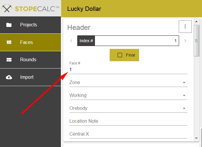
A list of fields follows the Index#, comprising drop-down lists established in Project Setup, coordinates, and other metadata. The full list is summarized below:
Zone
Working
Orebody
Location Note
*Central X
*Central Y
*Central Z
Date
*Shift
*Type
**Width
*Height
PrevFace
NextFace
Influence**
Recommendations
Start X
Start Y
Start Z
Line Dip
Line Azimuth
*Method
*Required fields, either for Save operation or for volume calculations
**Required for tonnage estimate attributable to face if Autocalc not checked (Width) or PrevFace and NextFace are not specified and Autocalc is not checked.
It's important to fill out as many fields as possible in the mine, or upon creation of a face in the office setting. If not needed for correct indexing and validation, they may be useful for filtering and reporting. Date is automatically filled out upon face creation, but it can be edited by clicking on the button in the right side of the Date box. A calendar will allow selection of the date and insert it in the proper format. The table below gives a brief description of each field in the Header section:
Variable |
Description |
Zone |
Major mine division or working area from Project list |
Working |
Name of development or stope from Project list |
Orebody |
Name of vein or other orebody from Project list |
Location Note |
Free-form: distance from a survey point or other note |
*Central X |
Face centerpoint X |
*Central Y |
Face centerpoint Y |
*Central Z |
Face centerpoint Z |
Date |
Creation Date |
*Shift |
From Project list |
*Type |
Stope, Slab, Face, Dummy, Split |
Width |
Measured face width in project units; if Autocalc Width is checked, that is, Width is assigned as the highest 'To' value in the face sample group, Width is corrected to horizontal width by Line Dip value |
*Height |
Measured face vertical height in meters |
PrevFace |
Previous Face# in development or sampling sequence |
NextFace |
Next Face# in development or sampling sequence |
**Influence |
In development , one half the distance to next face + half the distance to previous face, measured between centerpoints |
Recommendations |
Free-form geology or administrator note for display--instructions given at time of sampling to miners may go here. |
Start X |
Location X of starting point for sample line--used for displaying line as drill hole |
Start Y |
Location Y of starting point for sample line--used for displaying line as drill hole |
Start Z |
Location Z of starting point for sample line--used for displaying line as drill hole |
*Line Dip |
Inclination, sign convention used depends on user's visualization software, -90<0<90 unless vertical width (VW) method is chosen. |
Line Azimuth |
Sample line direction -- no provision for curved lines |
*Method |
HW, TW or VW -- determines how user defines width and height |
* Required STOPECALCTM fields
Fields required to enable STOPECALCTM calculations are asterisked. Others, such as StartX, Y, Z and Line Azimuth enable loading faces to mine visualization packages as drill holes and also enable more complete filtering in STOPECALCTM. Date is essential for any period reporting.
Width
Volume calculations depend on representative face dimensions. CRC recommends inserting a Width, the measured width of the working, from a tape or distance meter by taking the measure 50 cm or more from the face to be more representative of the final working width. Faces are often tapered after a blast. Width may be >total sample line width, but it should not in any case be less since it is a denominator in weighting calculations. In most cases, it will be desirable to make the width measurement exactly at the starting point, or as close to it as possible, even if that means sampling a short ways around the curve of the face. If that is not possible or advisable in a particular situation, the face width will exceed the sampled line width, requiring that the face width is specified manually and not calculated automatically. The Autocalc checkbox should be unchecked for this face. For additional discussion of face width and volume reconciliation see Getting Started.
Width can be autocalc'd using the greatest 'To' value in the face's group of samples by checking the Autocalc box. If the autocalc proxy for width is enabled, the width displayed in the Header section will be corrected by dividing 'To' by the absolute value of the cosine of the Line Dip value. In this way, the width is the horizontal width of the working and can be multiplied by Height to yield the Face Area value.
Height and Influence
The terms height and influence have different significance depending on whether a sample is from a stope, a raise or a drift. Since faces are two-dimensional, the term "influence" is used instead of length and is synonymous with "projection". It must be measured or estimated in order to obtain volumes. Each case is discussed in the following lines.
In development, height should be measured as closely as possible vertically from hard floor to an average crest point or arch of the roof. Influence is as-stated in the table above: it is based on the subhorizontal separation of faces.
If the sample line is taken across a stope back, then height is defined as the height of the slice to be extracted. Influence is, again, the horizontal projection of the face information, but for a stope it is used directly to estimate tonnage since the entire cut is treated as a production entity instead of individual rounds.
The Influence variable is required to attribute volume and tonnes to a face. For faces in a sill, these face tonnages are indicative only and are superseded as rounds are created in the Rounds section. Influence is the projection of the face in each direction, equal to the sum of 1/2 of the 3d distance to each adjoining face based on calculation from the face centerpoints. PrevFace and NextFace entries allow the user to choose the autocalc option for Influence and to calculate tonnage and grade attributable to each face. The program will calculate Influence automatically if PrevFace and NextFace faceid's are provided, otherwise Influence must be determined manually. It is permissible to derive an Influence from a single face. This situation is appropriate for slashes or slabs, or for the first and last faces of a sill or first and last channel in a stope.
If the Autocalc box is checked, then either PrevFace or NextFace, or both must have a listed Index#. If the box is not checked, then an Influence value must be entered (see above).